Analysis of NC milling process of typical disc sleeve parts
Table of Contents
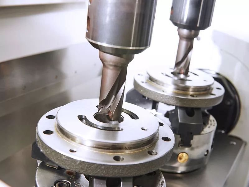
The CNC milling of typical disc sleeve parts must be processed at a machining center with a good cooling system. It has high requirements for blank quality, small machining allowance, and high machining accuracy. However, the general CNC milling machine tool is mainly used for the trial production of new products or parts with small production batches. It can be clamped once or twice on the machining center to complete all rough and finish machining processes. Suppose it is necessary to carry out the milling process of the disc sleeve parts. In that case, it is necessary to better understand the parameters of the machine tool, the tools used, the processing plant, etc., to control the milling process of the disc sleeve parts.
The arrangement principle of the processing sequence of the telecommunication disk sleeve parts was designed this time: rough first, then fine, surface first, hole first, and base surface first.
According to the above principles, the processing sequence of the part is determined as follows: milling the bottom surface, milling the outer contour around, flipping and clamping, milling the upper surface, rough milling boss, fine milling boss, rough milling convex cavity keyway, fine milling convex The keyway of the table cavity, drill the center hole, drill the 4xФ8.7mm threaded holes around the part, the depth of the tool shoulder is 20mm, and tap 4XM10.
This article is summarized and provided by the CNC engineer of Anpllo Company. It mainly discusses the thinking plan route of adopting the processing technology, the CNC milling machine tools, and the cutting tools summarized and described.
Process route scheme adopted
Process route scheme (1)
(1) Process 1: Manufacturing blank 90mm×90mm×40mm
(2) Process 2: Rough and fine milling of 6 faces to a size of 80mm×80mm×30mm
(3) Process three:
①Working step 1: Rough milling the contour of the boss, leaving a finishing allowance of 0.4mm on the side
②Working Step 2: Finishing the contour of the boss
③Working step 3: Roughly milling the arc keyway on the boss, leave a finishing allowance of 0.4mm at the bottom and side
④Step 4: Fine milling the arc keyway on the boss
⑤Step 5: Drill threaded hole 4xФ8.7 mm, shoulder depth 20mm
⑥Step 6: Tapping 4XM10, 12mm deep
(4) Process 4: Deburring
(5) Process five: inspection
(6) Process 6: Storage
Process route plan (2)
(1) Process 1: Manufacturing blank 90mm×90mm×40mm
(2) Process 2: Rough and fine milling of 6 faces to a size of 80mm×80mm×30mm
(3) Process three:
①Working Step 1: Drill threaded hole 4xФ8.7mm, shoulder depth 26mm
②Working step 2: Tapping 4XM10, 18mm deep
③Working step 3: Roughly milling the arc keyway on the boss, leave a finishing allowance of 0.4mm at the bottom and side
④Step 4: Fine milling the arc keyway on the boss
⑤Working step 5: Rough milling the contour of the boss, leaving a finishing allowance of 0.4mm at the bottom and sides
⑥Working Step 6: Finishing the contour of the boss Step 4: Deburring
(6) Process five: inspection
(7) Process six: storage
Process route scheme comparison
In CNC machining, the trajectory of the tool position relative to the workpiece movement is called the machining route. Principles for determining the processing route:
(1) The processing route guarantees the precision and surface roughness of the processed parts and has high efficiency;
(2) Make the numerical calculation simple and reduce the programming workload;
(3) The processing route should be the shortest, which can not only reduce the program segment but also reduce the empty tool time. From the comparison and analysis of the above schemes, we can see that the second scheme puts drilling and tapping in front, and then milling the plane after drilling and tapping is contrary to the division of the process, which is not conducive to the next milling process, so the comprehensive consideration is to choose the first scheme. Processing.
Determination of equipment and process equipment
Machine tool selection
Since this part is produced in small batches of one piece, there is no need to consider issues such as production efficiency as long as the corresponding equipment can be selected for processing on the premise that its accuracy requirements can be guaranteed. Still, to reduce the number of artificial tool changes, according to the existing For CNC machine tools, it is determined to choose the VMC850 series CNC vertical machining center produced by Dalian Machine Tool Factory Equipment Co., Ltd. The main technical parameters are as follows:
System configuration: FANUC
Worktable area (mm): 460×950 (500×1050)
Stroke (X-Y-Z) (mm): 800×500×550
Spindle taper hole: BT40
Main power (KW): 7.5/11
Spindle speed change system speed (rpm): 50-6000
Servo machine structure: Taiwan spindle, full protection, plastic-coated slide rail, electric cabinet air conditioner
Remarks: 16 hat-style tool magazines, 20 disc-style tool magazines
Fixture selection
When determining the clamping scheme, it is only necessary to determine the positioning and clamping method of the workpiece according to the selected processing surface and positioning datum and select the appropriate fixture.
(1) Special fixtures: Generally, various special fixtures produce relatively stable products and large batches to obtain higher productivity and processing accuracy. In addition to large-scale production, some special fixtures are also required in small and medium-sized batch production, but specific technical and economic analysis must be carried out during structural design;
(2) Universal fixture: A standardized fixture that can process different workpieces within a certain range is called a universal fixture. Its size and structure have been standardized, and it has certain versatility. This fixture has strong adaptability, can be used for various workpieces within a certain shape and size range, and is cheap. The disadvantage is that the precision of the fixture is not high, the production efficiency is relatively low, and it isn’t easy to clamp. Generally suitable for single-piece small batch production.
(3) Combined fixture: The combined fixture is modular. Standard modular components have high precision and durability and can be assembled into various fixtures. The fixture can be disassembled after use and left after cleaning to assemble a new fixture. Since the use of combined fixtures can shorten the production preparation cycle, the components can be used repeatedly and have the advantage of reducing the number of special fixtures;
Points to choose a clamping method
(1) Select the design datum of the box as the fine datum as much as possible; the selection of the rough datum should ensure that the machining allowance of the important surface is uniform so that the size and position of the unprocessed surface meet the requirements of the drawing, and it is easy to clamp;
(2) During the high-speed and powerful cutting of the machining center, the positioning datum must have sufficient contact area and distribution area to withstand large cutting forces and ensure reliable positioning and movement;
(3) The fixture itself should be positioned and installed on the machine tool with the reference groove or reference hole on the worktable of the machining center, which can ensure the fixed dimensional relationship between the workpiece coordinate system of the part and the machine tool coordinate system, which is different from ordinary machine tools. Important difference.
Based on the comprehensive analysis of the block seat, the blanks and parts are relatively regular and are clamped in a machine-use flat-mouth vise.
Tool selection
The choice of the cutting tool is one of the important technical contents in CNC machining. It affects the machining efficiency of the machine tool and directly affects the machining quality. The selection of tools during programming usually considers the processing capacity of the machine tool, process content, workpiece material, and other factors. The cutting tools used on CNC machine tools should meet the requirements of convenient installation and adjustment, good rigidity, high precision, and good durability. Basic requirements for knives:
(1) The rigidity of the milling cutter is better. The purpose of better rigidity of the milling cutter is twofold: one is the need to use a large cutting amount to improve production efficiency; the other is to adapt to the characteristics of the difficult adjustment of the cutting amount during the machining process of the CNC milling machine;
(2) The durability of the milling cutter should be high. Especially when a milling cutter has a lot of processing content, if the tool is not durable and wears quickly, it will not only affect the surface quality and machining accuracy of the part but also increase the number of tool adjustments and tool settings caused by tool change. It will also cause The working surface to be left with a knife step formed by the knife setting error.
In addition to the above two points, selecting the geometric angle parameters of the cutting edge of the milling cutter and the chip removal performance is also very important. Depending on the processing content, different specifications of cutting tools are required for processing. The material of this part is 45 steel, and the size of the blank and the size of the finished product are relatively sufficient. Considering the processing efficiency, the traces of the cutting tool, and the overlapping amount of the cutting tool.
Based on the above analysis, it is determined that the face milling cutter Φ120mm is used for milling six planes; the Φ12mm end mill is used for rough and fine milling of bosses; the Φ10mm end mill is used for rough and fine milling of key grooves on the bosses; Drilling; tapping M10 standard tap.
summary
For such parts, the CNC milling of disc sleeve parts can be carried out according to the above ideas and related parameters and tool settings. The main difficulty lies in considering the part design and material application comprehensively. If the abovementioned processing points are not considered, I think the scrap rate will remain high when the blank is formally processed on the machine. I hope the above content is helpful to you. This article is summarized and provided by the CNC machining engineer of Anpllo Company. If you have relevant needs, you can directly contact us for cooperation.


